5. Characteristics Of Brick
In general, the characteristics of brick reflect the way the brick are manufactured and the type of clay or shale used to make the brick. Generally, the harder a brick is, the longer lasting and more water proof it is. Brick used in construction must endure heat, cold, wetting, drying, ultraviolet, and chemical and corrosive actions. Of all the materials used in construction, brick is probably the most tested by time.
Since kiln-burned brick are fireproof, walls constructed of brick are given fire resistant ratings. That is, the wall is rated according to the amount of time it will withstand heat before failing. The American Society of Testing Materials (ASTM) has established tests for determining the safe ratings for masonry walls. The fire rating of a wall is usually less than the actual ultimate fire resistance of the wall. As a result there is a safety margin within which the builders can work.
There are many different kinds of brick available today for use in construction. The factors to be considered when selecting brick include composition, the manufacturing method, strength, appearance, color, special effects, and economy.
It is very important to select the type of brick with the right combination of features for a particular job.
Building Brick and Pace Brick. Building or common brick (ASTM C62) is made from ordinary clay or shale and burned in a kiln. Common brick do not have to meet special standards for color, design, or texture.
Common brick is sometimes known as kiln run brick and is used as filler brick or backing material on many construction jobs.
Older styles of kilns did not always provide uniform heat to all of the brick because of the design of the kiln, differences in the fuel used, and the location of the brick in the kiln. As a result, brick fired in the same batch often had different characteristics, depending on their location in the kiln. Because these variations appeared in each batch fired, each variety of brick received a name such as clinker, red, soft, salmon, rough hard, straight hard, and bloat. As brick kilns improved and the control of heat became more uniform in the burning area, the old types of common brick were no longer made.
Typically in the brick plants indigenouous to the Pacific Northwest a true common brick is no longer manufactured. Its place in construction is filled by "classed" or "service grade'" products. This nomenclature indicates brick suitable to fulfill the role of "commons" but not able to meet face brick specifications.
The term face brick originates from the fact that the brick is used in the front or face side of a wall. The material used and the burning of the brick must meet controlled specifications if the brick are to be used as face brick. The size of the brick must also be within the tolerances established by the American Society for Testing Materials. All face brick must meet standards for absorption, uniformity, and strength. The color and texture must meet the specifications established for the variety of brick being made.
Brick Sizes. One of the most important recent developments in the brick industry is the range of sizes in which brick can be obtained. The increased number of sizes means that the laying of brick can be more economical as the mason covers more area using a brick larger than the standard size. There is more energy exerted to lay brick larger than the standard size but not enough to result in excessive fatigue for a normal workday (unless, of course, the brick unit is exceptionally large). The oversized brick is popular in construction today since with their use, square foot production increases on some jobs.
Until recently, only three sizes of brick were available, standard, Norman and Roman. Brick now can be obtained in the following sizes: the thickness or bed depth may range from a nominal 3 inches to 8 inches and even 12 inches; the height may range from a nominal 2 inches to 6 inches; and the length may be up to 6 inches.
Before starting any job, consult with local brick manufacturers or supplies to be sure that the brick selected for the job is available in the areas.
The names for the different brick sizes are not the same throughout the industry (with the exception of the Standard, Roman, and Norman sizes). Individual manufacturers often give names to their own lines of brick sizes.
To avoid confusion and the risk of getting the wrong size, it is good practice to identify the brick first by its dimensions and then by its name. Calling out width, height and length in that order.
The modern brick is made for use in the modular grid system of building. Standards for modular dimensions have been approved by the American Standards Association for all building materials. These dimensions are based upon a 4-inch unit of measure called the module. This module is used as a basis for the grid system which must be used when two or more different materials are to be used in a construction job. Any building construction in which the size of the building materials used is based on the 4-inch grid system is called modular design.
Most modern brick are produced in modular sizes. In modular design, the nominal dimension of a masonry unit (such as a brick or a block) is understood to mean the specified or manufactured dimensions plus the thickness of the mortar joint to be used. That is, the size of the brick is designed so that when the size of the mortar joint is added to any of the brick dimensions (width, height, and length) the sum will equal a multiple of the 4-inch grid. For example, a modular brick whose nominal length is 8 inches will have a manufactured dimension of 7 1/2 inches if it is designed to be laid with a 1/2-inch mortar joint, or 7 5/8 inches if it is designed to be laid with a 3/8-inch joint.
Brick sizes in the Pacific Northwest have evolved for one reason or another into a modular system that is slightly different than what is known as modular in other parts of the United States.
5.1. Building Brick. The term "building brick" usually refers to the common or standard or basic unit made of clay. The quality of a building brick is judged on its physical characteristics such as grade, compression, strength, modulus of rupture, total absorption, initial rate of absorption and visual inspection upon delivery.
The most widely used specification for building brick is ASTM C62.
Building brick: available standard sizes and shapes
5.1.1. Basic Use. 1) Back-up brick, 2) Service grade brick, and 3) Classed ware.
5.1.2. Grade. There are three grades of building brick: SW, MW, and NW. These grades are sometimes known as Severe Weathering, Moderate Weathering, and None Weathering.
The SW grade is the unit intended for use where a high degree of resistance to frost action and disintegration by weathering is desired, such as a clay unit that may be exposed to frost action when it is permeated with water.
The MW grade of brick is the unit intended for use where a moderate degree of resistance is required and where it is not likely to be permeated with water when exposed to temperature below freezing.
The NW grade is a unit for use as backup for interior masonry. It is a unit that may disintegrate when subjected to freezing and thawing cycles.
5.1.3. Compression. This is the load applied upon a brick unit in its normal position in accordance with ASTM specifications. Brick shall develop not less than 1500 psi for NW grade, 2500 psi for MW grade, and 3000 psi for SW grade on an average of five samples. When the designer desires greater capacities than these for brick, they should be so specified in addition to the ASTM specification.
5.1 .4. Total Absorption. The total absorption of brick units is measured in two different manners. First, a 24 hour cold water exposure, from which the amount absorbed is recorded as a percentage of total weight of the dry unit. Secondly, a five hour boiling test, from which the amount absorbed is also recorded as a percentage of the total weight of the dry unit. The ratio of these two is the cold water/boiling water ratio or C/B ratio.
In ASTM Standards, both the five hour boil and the C/B ratio have maximum allowable limits for each grade.
The C/B ratio is considered as a measure of the ratio of durability. It presumably is a measure of the ratio of easily filled pores to the total available tillable pore space.
5.1.5. Rate of Absorption. The rate of absorption is an entirely different measure from the total absorption. It is a measure of the amount of water which a brick will absorb in a period of one minute, i.e. a measure of the rate at which the water is initially absorbed. It is sometimes called initial rate of absorption and is expressed as "grams per 30 square inches per minute." It is not a measure of, and cannot be related directly to total absorption.
This physical characteristic of a brick unit is important for a number of reasons.
First, if the absorption of a brick unit exceeds the proper rate, there normally will not be a good bond with mortar. Tests have shown that the ideal initial rate of absorption is in the range of 10 to 12 grams up to about 20 grams per minute.
Second, as brick units are laid in the wall the rate of laying becomes critical. Water will be lost from the mortar bed before the brick is placed on it.
Third, an excessively high initial rate of absorption may require tapping on a brick wall, disrupting the bond between brick and mortar.
Fourth, an extremely high initial rate of absorption will have a tendency to dry the mortar so quickly that it will not retain the proper amount of water for high strength and good bond.
When an initial rate of absorption of brick unit exceeds 20 grams per minute it is standard practice, highly recommended, and a code requirement, that these units be wet to reduce their initial rate of absorption so as not to exceed 20 grams per minute at the time of laying.
This wetting perferably should be done about 24 hours before the brick units are laid in the wall so that the water will have filled the pores and will have reduced the initial rate of absorption, but will not leave the brick surface wet.
5.1.6. Color end Texture. Building brick are manufactured in a variety of colors and textures. However, the color and textures are supplied at the option of the brick manufacturer unless some specific requirement has been stated, or mutually agreed upon, between the buyer and seller prior to delivery.
5.1.7. Visual inspection. The building brick delivered to the site shall, by visual inspection, conform to the requirements as specified by the purchaser if special requirements have been stated in addition to ASTM, or comply with the sample or samples supplied to the purchaser. Minor flaws, indentations, surface cracks and minor chips resulting from the customary handling of building brick shall generally not be deemed grounds for rejection in the wall. The wall face shall be free of imperfections detracting from the appearance when viewed from a distance of 30 feet.
Unless otherwisa agreed upon by the manufacturer or the seller, building bricks, when delivered to the job site, shall contain not less than 95 % whole brick (according to ASTM C62).
5.1.8. Appearance. If brick having a particular appearance as to color, texture, finish, uniformity or freedom from cracks, warpage, exposed stones, pebble or particles of lime are desired, such requirements should be called out and the brick preferrably specified according to ASTM C216.
5.1.9. Remarks. In the Pacific Northwest a true common brick is no longer manufactured, Its place in construction is filled by "classed" or "service grade" products. This nomenclature indicates brick suitable to fulfill the role of "commons" but not able to meet face brick specifications.
The standard common building brick color will be a terra cotta red. However, units of buff, salmon, orange, red or brown may be supplied. The brick texture is usually smooth, but it may also be scored, wire-cut or whatever textures are agreed upon prior to delivery. Listed in ASTM C62 and it is to be noted that the dimensions are plus or minus the specified size.
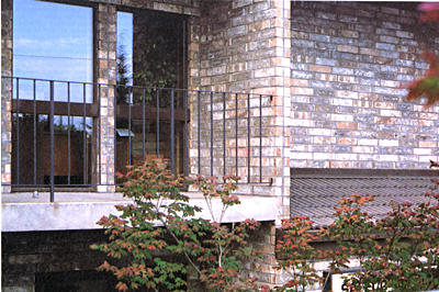
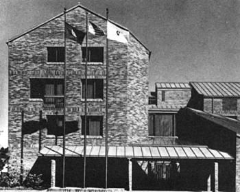
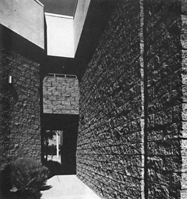
Adobe texture face brick.
Sam Gotter office building, Tigard, Oregon5.2. Face Brick. The term face brick originates from the fact that the brick is used in the front or face side of a wall. The material used and the burning of the brick must meet controlled specifications if the brick are to be used as face brick. The size of the brick must also be within the tolerances established by the American Society for Testing Materials. All face brick must meet standards for absorption, uniformity, and strength. The color and texture must meet the specifications established for the variety of brick being made.
Facing brick is brick of clay, shale or mixture thereof complying with ASTM C216. They are units manufactured for the distinct purpose of becoming an exposed face of a masonry wall. The characteristics are judged basically by grade, type, compression, total absorption, rate of absorption, color, texture, size, warpage, and visual inspection.
5.2.1. BasicUse. 1) Veneer, 2) Cavitywalls, and 3) Multi-wythe reinforced walls.
5.2.2. Grade. There are two grades of facing brick: SW and MW. The SW grade of brick is the brick intended for use where a high and uniform degree of resistance to frost action and weathering is desired and where a brick unit may be exposed to frost action when permeated with water. The MW grade brick is the unit intended for use where a moderate and lesser degree of resistance to frost action is required and where it is unlikely to be permeated with water when exposed to temperatures below freezing.
There is no NW grade since these brick are not intended to be used as backup.
5.2.3. Type. There are three types of facing brick:
Type FBS, Type FBX,and Type FRA.
Type FBS -- brick for general use where wide color ranges and greater variation in sizes are permitted.
Type FBX -- the brick for general use in exposed faces of exterior or interior masonry walls and partitions where a high degree of mechanical perfection, narrow color range and minimum permissible variation in size are required.
Type FBA -- brick manufactured and selected to produce characteristic architectural effects resulting from non-uniformity, color, size or texture of the indidividual units.It is specifically called to the attention of the designer that when no type of facing brick has been specified, the basic requirements of Type FBS shall govern.
5.2.5. Visual inspection. ASTM C21 6 states that all brick units shall be made of clay, shale or fireclay materials and that any admixtures or colors used in giving a special color to a unit shall be uniformly distributed through the entire body of the brick. in other words, it may not be merely a surface color unless specifically agreed upon by the purchaser and seller. It is also stated that the brick shall be free of cracks and other defects that will interfere with the proper seating of the brick or that will impair the strength or the permanence of the construction. The faces of brick units shall be free of imperfections detracting from the appearance of a sample wall when viewed from a distance of 15 feat for type FBX and from a distance of 20 feet for types FBS or FBA.
5.2.6. Color and Texture. Facing brick comes in a variety of colors and textures. It is therefore ex tremely important that the designer and specifier make an exact color and texture selection and state it carefully in the specifications. Face brick units can be supplied through a full range of colors.
ASTM 216
Table 3. Maximum permissible extent of
chippage from the edges and corners of rinished
face or faces into the surface
Chippage in inches (millimetres) in from: edge corner Type FBX 1/8 (3.2) 1/4 (6.4) Type FBS
(smooth)11/4 (6.4) 3/8 (9.5) Type FBS
(rough)25/16 (7.9) 1/2 (12.7) Type FBA as specified by the purchaser 1Smooth texture is the unbroken natural die finish.
2Rough texture is the finish produced when the face is sanded, combed, scratched, or scarified or the die skin on the face is entirely broken by mechanical means such as wire-cutting or wire-brushing.
ASTM C216
Table 4. Percentages of shipment that may be allowed chippage over maximum permissible in Table 4
Percentage allowable Chippage in inches (millimetres) in from: edge corner Type FBX 5 1/4 (6.4) 3/8 (9.5) Type FBS
(smooth)10 5/16 (7.9) 1/2 (12.7) Type FBS
(rough)15 7/16 (11.1) 3/4 (19.1) Type FBA as specified by the purchaser
ASTM C216
Table 5. Tolerances on Dimensions
Specified dimension, Inches (mm) Maximum permissible variation from specified dimension plus or minus,
Inches (or mm)Type FBX Type FBS 3 (76) and under 1/16 (1.6) 3/32 (2.4) Over 3 to 4
(76 to 102), incl3/32 (2.4) 2/16 (3.2) Over 4 to 6
(102 to 152), incl2/16 (3.2) 3/16 (4.7) Over 6 to 8
(152 to 203), incl5/32 (4.0) 4/16 (6.4) Over 8 to 12
(203 to 305), incl7/32 (5.6) 5/16 (7.9) Over 12 to 16
(305 to 406), incl9/32 (7.1) 3/8 (9.5)
ASTM 216
Table 6. Tolerances on Distortion
Maximum face distortion,
Inches (mm)Maximum permissible distortion,
Inches (or mm)Type FBX Type FBS 8 (203) and under 1/16 (1.6) 3/32 (2.4) Over 8 to 12
(203 to 305), incl3/32 1/8 (3.2) Over 12 to 16
(305 to 406), incl1/8 (3.2) 5/32 (4.0) It is suggested that the designer or specifier check with manufacturers regarding terminology of textures so these may be specified properly.
Northwest available textures (not all sizes) 1) Mission (wire cut), 2) Smooth, 3) Deformed, 4) Rockface, 5) Scratch or Rug, and 6) Used Type.
5.2.7. Warpage. Facing brick will come in a variety of sizes and shapes which must be carefully called out by the specifier, and a sample should be obtained containing 10 brick units which will include the extreme range of color and size of the brick to be supplied. ASTM C216 lists the deviations from specified dimension, and these are listed as plus or minus. The limits for warpage are not plus or minus as are the deviations in length. They are measured by placing the unit on a table and checking the deviation from the surface.
5.2.8 Special Shapes, refer also to manufacturer's catalog
5.2.9 Standard Shapes and Nominal Sizes
#1 Standard solid 4x3x8
#2 Standard 4x3x8
#3 Roman 4x2x12
#4 Norman 4x3x12
#5 Econ 4x4x12
5.3. Hollow Structural Brick. 5.3.1. Description. The ability to build masonry walls taller and thinner results in many user benefits. Tall slender hollow structural brick walls provide initial cost savings, are space saving, and permit increased vertical clearance. This product is possible by modification of ASTM C652 with the ICBO Report #2730.
5.3.2. Basic Uses. 1) Reinforced structural walls and 2) Prefabricated panel system.
5.3.3 Grade Designation
See table II below
5.3.3. Grade Designations
(Table No. II - Physical Requirements
ICBO Report NO. 2730)
Minumun Compressive Strength (brick flatwise) (psi Net Area) Maximum Water Absorption by
5-h boiling (percent)Maximum Saturation Coefficient Designation Average of 5 brick Individual Average of 5 brick Individual Average of 5 brick Individual Grade I Brick (exposed) 3000 2500 17.0 25.0 0.78 0.080 Grade II (not exposed) 2500 2000 no limit no limit no limit no limit The saturation coefficient of C/B Ratio, is the ratio of absorption by 24-hour submersion in cold water to that after five-hour submersion in boiling water.
5.3.4 Compressive strength See ICBO Report #2730.
5.3.4 Compressive strength
(ICBO Report No. 2730)
Designation Compressive Strength (p.s.i. net area) f'm Average of 5 bricks Individual Minimum (See footnote number one) Type 1 (exposed) H 3000 3000 to 3999 2500 1800 H 4000 4000 to 4999 3200 2000 H 5000 5000 to 5999 4000 2300 H 6000 6000 to 6999 4800 2600 H 8000 8000 to 8999 6500 3300 H 10,000 10,000 to 19,999 8500 4000 Type II only
(not exposed)2500 to 3000 2000 1500 1Where the assumed f'm exceeds 2600 pounds per square inch, field tests in accordance with Section 2404 (c) 2 shall be required.
5.3.5. ICBO Report No. 2730 Minimum Thickness of Face Shells and Webs.
Coring: (a) No part of any hole shall be less than 3/4 inch from any edge of the brick, except for cored shell hollow brick and double shell hollow brick. Cores greater than 1 square inch in cored shells shall be not less than 1/2 inch from any edge. Cores not greater than 1 square inch in shells cored not more than 35 percent shall be not less than 3/8 inch from any edge.
(b) Cells for reinforcement shall be not less than 2 inches in any dimension nor less than 5 square inches in area when containing one rebar nor 7 square inches for two bars or spliced bars.
(c) Face shells and webs shall be not less than as indicated.
5.3.5. ICBO Report No. 2730
Minimum Thickness of Face Shells and Webs
Nominal Width of Unit (inches) Face Shell Thickness (inches) End Webs (inches) Web Thickness per foot total (in./Ft.) Solid Cored or Double Shell 3 and 4 3/4 - 3/4 1 5/8 6 1 1 1 2 1/4 8 1 1/4 1 1/2 1 2 1/4 10 1 3/8 1 5/8 1 1/8 2 1/2 12 1 1/2 2 1 1/8 2 1/2
5.3.6. Maximum Saturation Coefficient, If the average compressive strength is greater than 7000 psi (55.2 MPa) or the average water absorption is less than 8.0 percent after 24-h submersion in cold water, the requirement for saturation coefficient shall be waived.
5.3.7. Texture. Mission (wire cut) is only available texture.
Kent City Hall, product: hollow structual brick,
Architect: Fred Bassetti and Company
Kent City Hall Library
5.3.8 Shapes and Sizes. For special shapes and sizes refer to manufacturers catalogs.
Carco Theater, Renton
Product: Hollow Structural Brick
Architect: ORB, Architects, Renton
5.3.9. Available Standard Shapes
4" Stretcher -- #1
4" Bond Beam -- Similar to #6
4" Half
4x4x4 Lintel -- #3
4" 45 degree Squint -- ;#2
4" "L" Corner -- #4
6" Stretcher -- #5
6" Bond Beam -- #6
6" Half -- 5 1/2 x 5 1/2 Unit
6' Corner -- #7
6x4x6 Lintel -- Similar to #3
6x8x4 Lintel -- Similar to #3
6" 45degree Squint -- Similar to #2
8" Stretcher -- #9
8" Bond Beam -- #8
8" Half -- 7 1/2 x 5 1/2 Unit
8x8x4 Lintel -- Similar to #3
5.4 Paving Brick.
5.4.1. Paving brick is being manufactured in the Northwest according to ASTM C902 specification modified by local conditions.
5.4.2. Basic Use. 1) Dry set paving for light traffic, 2) Mortar installed paving for light traffic.
5.4.3. Compressive Strength. Average minimum 8000 psi according to ASTM C902.
5.4.4. Absorption Rate. Less than 8 % with 24-hour cold water test (local condition).
5.4.5. Tolerances. 2% size variation, 1 % face warpage.
5.4.6. Texture. Smooth and mission (wire cut).
5.4.7. Skid/Slip Resistance.
(ASTM C902)
(1)
Abrasion Index, Max.(2)2
Volume Abrasion
Loss, Max, cm3/cm2Type I 0.11 1.7 Type II 0.25 2.7 Type II 0.50 4.0 1Skid/slip resistance should be considered by the purchaser for uses of brick where pedestrian traffic is anticipated. Methods of testing this characteristic are under study and it is hoped that a specification for this property can be added in future revisions of this standard when suitable test methods are developed.
2The brick should meet the requirements of either column (1) or (2).
5.4.8. Standard Sizes and Shapes (Special sizes available, please contact manufacturers)
5.5. Miscellaneous Brick Products.
5.5.1. Customized Brick. Customized shapes such as closures for English bond corners, radial brick, sills and copings, etc. are available as special shapes. Consult with manufacturers.
The most unusual examples of customized bricks are sculptured pieces handcrafted from the green clayware before firing. The unburned units are firm enough to allow the artist to work freely without damage to the brick body, but sufficiently soft for carving, scraping, and cutting. After execution of the design, the units are returned to the plant for firing and the relief is permanently set in the brick face.
Sculptured brick are examples of custom units
Sculptured brick are examples of custom units
5.5.2. Glazed Brick. Brick with glazed surfaces should be specified under the glazed brick specification ASTM C126, and any requirements in excess of ASTM must be so designated. For example, if especially fine work is desired with extremely close joint requirements, tolerances must be specified that are less than those listed in ASTM.
It is noted that a brick may be either solid or cored at the option of the seller unless specified other wise prior to delivery. A cored brick shall be solid for at least 75 % of the gross cross section and have no core holes doser than 3/4" to the edge of the brick
5.5.3. Firebrick. Refectory brick or firebrick, are used in furnaces, chimneys, firebexes, and ovens. The fire clay from which they are made has a much higher fusing point than that of ordinary clay or shale. Once the initial kiln firing has been accomplished, firebrick are extremely resistant to high temperatures without cracking, decomposition, or distortion, Firebrick are normally heavier and softer than other units and are produced in a slightly different size to be laid with a thin coating of fire clay mortar in lieu of standard mortar joints. Fire clays typically burn to a white or buff color.
5.5.3.1. Basic Use: Low duty firebrick.
5.5.3.2. Specifications: ASTM C-27-70, pyrometric cone 15 + modulus of rupture 600 + psi.
Firebrick ins
tallation
Clay Masonry Products Terra Colta
(Ceramic Veneer)1) General
2) Physical Properties
3) Standard Shapes
4) Examples Of Shapes Which Are Still Available
1. General
The use of burned clay ware in the form of brick, tile or pottery has been uninterrupted and universal from the dawn of civilization to the present day. The use of burned clay in the form of architectural terra cotta has been more sporadic and local. Its unequaled merits as a building material were fully appreciated by the Greeks and Tuscans who, two thousand years ago, used it to face the perishable stone in some of their temples. Centuries passed, during which the art of making architectural terra cotta seems to have been confined to short periods and to a few localities. In modern times the architect -- working with the responsive and enterprising manufacturer, rediscovered, improved and gave to an appreciative public this most durable and versatile building material.
Terra Cotta Ornamentation
While architectural terra cotta has been used as a decorative veneer for centuries, today's use is limited to restoration work. The name itself, which means "fired earth," dates from Roman antiquity. Hand-molded slabs with either plain or sculptured surfaces are still produced in the traditional manner. Modern methods of production now offer machine-extruded units as well. These mechanically fabricated pieces, usually referred to as "ceramic veneer," may have a smooth-ground surface, or may be beveled, scored, scratched, or fluted. Both the hand and machine-made types may be glazed in clear, monochrome, or polychrome colors and in matte, satin or gloss finishes. Both are custom products, and are more in demand today for restoration work than for new construction.
Terra Cotta Dome
The backs of veneer slabs may be flat or ribbed depending on the method of attachment to be used. Adhesion-type veneer is bonded to the backup material with mortar and requires no supplementary support. Its thickness is limited to 1 1/4 in. by most current building codes; its maximum face dimension to 36 in.; its area to 720 sq. in.; and its weight to 15 lb/sq. ft. Anchored-type veneer, usually 1 5/8 in. or greater in thickness, is attached by mortar bond and metal ties. Size and area limitations are accord ing to UBC requirements.
2. Physical PropertiesModern terra cotta possesses many superior qualities and it may be economically made in an endless variety of forms and colors; if well made, properly set and carefully painted, it is permanently enduring and resists successfully the ravages of water and fire; it combines lightness with strength and beauty with usefulness.
Attention is called particularly to the fact that considerable variations in sizes of similar sections may necessitate changes in both jointing and construction. Hence, none of the plates may exactly apply if the scale is reduced or increased.
Terra Cotta (Ceramic Veneer) Faced Building
The characteristics peculiar to architectural terra cotta and the extreme difficulties encountered in the vagaries of clay before it is finally conquered and forever fixed by fire can hardly be understood by those who have not been engaged in its manufacture. Therefore, harmonious cooperation between designers and manufacturers is imperative in order to produce the best results. Unfavorable shapes or dimensions, or arbitrary arrangement of engaging or supporting materials, may not only increase the cost of production and of erection, but may also produce unsatisfactory results, both aesthetically and constructively.
3. Standard Shapes
Many standard shapes are still available as stocked items. Below are examples of available sill shapes and coping shapes.
Concrete Masonry Products
1) History Of Concrete Block
2) Manufacturing Process
3) CMU Today
4) Properties & Characteristics
5) Types Of Concrete Masonry Units
6) CMU Shapes
1. History Of Concrete Block
Concrete Masonry Units are commonly referrred to today as "CMU's" or Concrete Blocks" by most writers of specifications, architects, engineers, and builders. The modular masonry building material associates with other concrete building materials because the end product is a hardened material primarily from portland cement, graded aggregates, and water. Its modular size and product characteristics have found modular concrete units a home with stone and clay materials used widely in masonry construction.
Since 1882 when the first concrete block was molded in a manual process, the industry has incorporated a high degree of automation. Harmon S. Palmer is generally credited with the development of the first commercial process for manufacture of concrete block in the United States. Palmer patented the basic principle of the hollow concrete building block machine with removable cores and adjustable sides in 1900. Palmer's concrete blocks were poured at the job site to save cost of transportation and eliminate breakage in handling. The blocks were quite large in size measuring 30' x 8" x 10" made from cement, sand, and water. The units were so large and heavy they had to be set in the wall with the aid of a hand cranked derrick.
Block machine at the turn of the century
A few years following Palmer's process the first hand tamp block machine (circa 1904) was developed. The equipment consisted of vertically placed cores and collapsible sides for block removal. Cement and aggregates were hand mixed, then shoveled into the mold and hand tamped around the core. The CMU varied in consistency and quality from unit to unit and generally measured 24" x 12" x 8". Three men working at top speed could turn out 200 block in a 10 hour day on this first machine.
In the early 1900s high costs and scarcity of competing materials made it natural for the concrete masonry industry to develop. One concrete block in 1906 replaced 28 common brick as an alternative product. Builders turned to this new material as a partial solution to their problems. Domestic concrete block manufacturers had several cost advantages over competing materials. Freight charges on lumber, stone, and usually on brick were greater than block, which was locally manufactured utilizing readily available materials. Growth of the concrete industry closely paralleled that of the Portland Cement industry during the first few years following 1900 thus creating reasonable prices for cement.
In 1904, Herman Besser used a hand manufacture block machine. His son designed and engineered their first automated block machine. The Besser Company is considered a pioneer in marketing concrete block manufacturing equipment and their developments are viewed as key milestones in the history of manufacturing concrete masonry units.
A breakthrough came in 1909, when a machine was developed that featured power tamping and self discharging mixer and skip loader, eliminating the laborious job of hand tamping.
In 1939, Besser introduced a radically new production method of "vibration under pressure," a system which eliminated costly wear on the facing liner of the machine associated with tamping.
In summary, the milestones mentioned above are essential for one to fully appreciate the manufacturing technology incorporated into our modern day automated concrete products manufacturing facilities. In the Pacific Northwest, block producers have fallen favor to two equipment manufacturers: The Besser Company in Alpena, Michigan, and Columbia Machine, Inc., Vancouver, Washington.
Handling of aggregates in a modern CMU plant
Production has changed from large cumbersome units produced one at a time in crude metal forms at the job site requiring large quantities of labor, to smaller high quality modules manufactured in large volume at highly automated facilities. Portland cements used in concrete have been greatly improved since the early years and quality of aggregates along with their gradation improvements have enhanced the concrete masonry industry
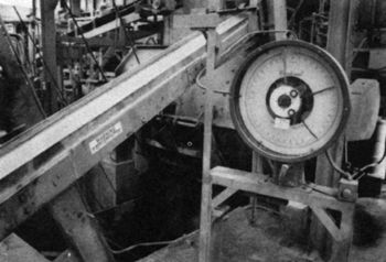
2. Manufacturing Process
Concrete masonry units are made mainly of portland cement, graded aggregates, and water. Depending upon specific requirements, the concrete mixtures may also contain other suitable ingredients such as an air-entraining agent, coloring pigment, and siliceous and pozzolanic materials.
Manufacturing process diagram
Mass production has contributed to the relatively low cost of quality concrete masonry units. In many production plants some phases of the manufacturing process are completely automated.
Briefly, the manufacturing process involves the machine-molding of very dry, no-slump concrete in to the desired shapes, which are then subjected to an accelerated curing procedure. This is generally followed by a storage or drying phase so the moisture content of the units may be reduced to the specified moisture limits prior to shipment. The concrete mixtures must be carefully proportioned and their consistency controlled so that texture, color, dimensional tolerances, and other desired physical properties are obtained, High-strength units have concrete with higher cement contents and more water, but still have no slump, Automatic machines consolidate, mold, and compact these concretes by vibration and pressure.
Acceleration curing is utilized by the concrete masonry industry, with variations according to local plant requirements and raw materials used, The common type of curing provides for heating the block in a steam kiln at atmospheric pressure to temperatures ranging from 120 to 180 degrees F. for periods up to 18 hours, Atmospheric pressure methods may require subsequent accelerated drying treatment of a period of natural drying in the storage yard under protective cover. A variation of this low-pressure curing is the carbonation stage, which is added to reduce the shrinkage characteristics of the masonry units.
Following steam curing and gas drying the units are placed onto wooden pallets and stored for future shipping.
2.1. Handling and Storage of Aggregates. Proximity of a production facility in relationship to its aggregate source is very important to the success of a block manufacturing company. Both sands and gravels are trucked into the plant and stored separately. Pumice aggregates are brought into the Northwest either by truck or rail. Availability of plentiful, highly uniform, graded materials is essential, While aggregate materials are brought in directly from the pit any contained moisture is accommodated for through meter readings during the batching process.
Cements are trucked into the production plant and stored in silos separate from other materials and moisture to reduce possibility of contamination.
2.2. Batching and Mixing. Metering and weighing systems for batching concrete vary widely depending on the equipment manufacturer. Batching the right proportions of sand, gravel, pumice, cement, and water may be semi or fully automated and must be given recognition for the role it plays in relationship to quality of the end product. Integral colored concrete masonry units are manufactured by adding coloring oxides during the mixing process.
CMU plant batching and mixing
2.3. Handling Wet Mixes. This element is mentioned only to point out there is a variety of equipment available for handling concrete while in its plastic stage. Some facilities operate in a vertical fashion where the mixer is mounted high off the ground placed directly above the block machine hopper, In most cases the mixer is located near ground level wherein various conveyors or bucket type of skip elevators are employed.
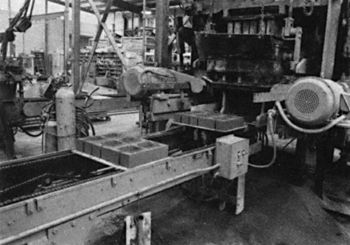
2.4. Block Machines, Molds and Dies. The work horse of the concrete unit manufacturing facility is the block machine. In the Northwest either "Columbia" or "Besser" machines are used. Many plants have only one block machine on line, however, because they last many years and are quite expensive some plants have modified their facility to accommodate more than one machine when equipment is upgraded.
Block machine in operation
Block machines are designed to employ the use of molds and dies in forming and shaping modular sized units, A wet no slump mix enters into the machine wherein it is vibrated and compressed into two or more units during each machine cycle. Block machines making three units per pass have become the industry's standard over the years, however, machines producing larger quantities are available.
Molds and dies have been developed to accommodate a multitude of shapes and sizes, Companies tend to make readily available those units where volume justifies tooling and die costs. Customer demand plays a large part in regionalizing manufacturer product lines throughout the U.S.
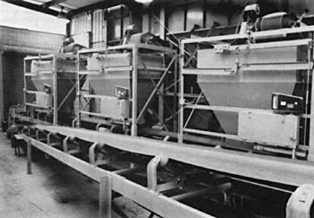
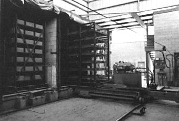
2.5. Transfer Equipment and Kilns.
Automation has contributed substantially to improvements in concrete masonry unit quality. Constant high quality products are moved by transfer equipment from the block machine into the steam and drying kilns and out of kilns ready for palletizing.
While mixes, block machines, and molds and dies play important roles in the physical properties and characteristics of CMU's, the kiln curing and drying processes are of vital importance. Following ASTM requirements for unit and composite strengths along with dimensional tolerances and moisture content standards, the block manufacturer creates atmospheric conditions inside of kilns using steam and temperature combinations conducive for accelerating concrete curing.
2.6. Palletizing and Storage. Steel pallets large enough to handle three 8x8x16 standard size c.m.u.'s are used to transfer block throughout the curing process. At the end of the automation line c.m.u.'s are placed either manually or mechanically onto wood pallets. An automated machine for palletizing is called a cuber and is operated by one person, versus manual stacking by two or more people.
An important item to point out in storing c.m.u. s is the need for light weight block to be kept dry so that ASTM moisture content specifications are met.
3. CMU Today
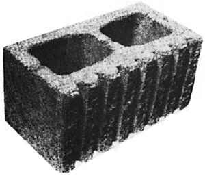
The dominant unit manufactured today is the 8x8x16 inch nominal module. It is curently manufactured as a two-core unit for reasons of providing for vertical reinforcing, lighter weight and balance in pick-up by the mason. Filled cell insulation can also be added in the block cores. This unit has gained popularity for the following reasons:
a) An optimum relationship of weight and size.
b) This unit bonds easily at corners as the width is half of the length allowing for running bond.The materials used in the manufacture of concrete block in the N.W., include portland cement, sand, gravel, and lightweight aggregate. The specific lightweight aggregate available in this area is pumice.
Block are manufactured as Lightweight units (less than 105 lbs/cu ft.) or medium weight (105-1 25 lbs/cu ft.). The density requirements are included in ASTM C-90.
Lightweight block utilize either all pumice aggregate or a combination (usually 50/50) of pumice and sand and gravel. Full pumice block provide superior fire resistance and energy saving properties, but are lower in compressive strength.
Another lightweight block manufactured is the 50/50 unit which is the dominant type block in the NW. This block provides overall construction economy because of its strength and weight. Normal Weight block are manufactured with all sand and gravel aggregate. These units have slightly less shrinkage and are denser than light weight block. They do weigh more which increases the laid in place cost somewhat
Freshly molded units are transferred into
the low pressure steam and drying kilns4. Properties and Characteristics of CMU
The infinite number of uses of concrete masonry are limited only to the imagination of the building designer. Few other materials have its fire-resistive qualities; few can match its structural strength. In a new era of energy saving consciousness it is finding much appreciation for its thermal resistive properties, not to overlook its effective ability to act as a barrier to the transmission of sound. Architecturally, it has embellished the finest of modern structures. With inflation leaping out of sight late in the twentieth century, concrete masonry's freedom from maintenance, and its fire resistance are other important features of this building material.
Color. Concrete block can be manufactured with integral color. Mineral oxide pigments are used to accomplish this. The normal colors possible are buff, red, brown, and yellow.
4.1 Texture: Texture in block is dependent upon the aggregate types and blend used in a particular mix as well as the water content during the molding process. Smooth units may have a nearly closed face texture (wipe) or very porous and open appearance. Split Face and Striated (Scratch) Face units have face textures created mechanically by a fracturing or combing process.
4.2. Hollow Load-Bearing Block. This section covers the standard hollow core concrete block. Such units are less than 75% solid. ASTM C-90 is the most widely used hollow block specification.
4.2.1. ASTM C-90 Northwest Modifications.
The typical concrete masonry unit manufactured in the Northwest is a Grade N block, Grade N units require a minimum compressive strength of 1000 p.s.i., average (3 units) gross area. This equates to a net concrete strength of over 2000 psi. since the block is approximately 50 % void area.
Some confusion arises over the compressive strength portion of the specification. Many specs call for the compressive strength of the concrete masonry unit to be 1350 p.s.i. rather than 1000 p.s.i. This is improper as 1350 p.s.i. is the wall design strength allowable with Grade N units. This value incorporates the strengths of the mortar and grout as well as the block into one design value based on net area.
Another ASTM C-90 requirement that stirs up much controversy, misunderstanding and wrong application is that concerning the type classification of concrete masonry units. C-90 states that there are two types of units for each grade: Type I, Moisture- Controlled Units, which shall conform to the moisture content requirements of Table I, and Type II, Non Moisture-Controlled Units, which need not conform to the moisture content requirement shown in Table 1.
ASTM C-90
Table 1 Moisture-Content Requirements for Type 1 Units
Linear Shrinkage Moisture Content, max, % of Total Absorption (Average of 3 Units) Humidity Conditions at Job Site or Point of Use Humida Intermediateb Aridc 0.03 or less 45 40 35 From 0.03 to 0.045 40 35 30 0.045 to 0.065, max 35 30 25 aAverage annual relative humidity above 75 %
bAverage annual relative humidity 50 to 75 %
cAverage annual relative humidity less than 50 %
Table 2 Strength and Absorbtion Requirements
Note -- To prevent water penetration protective coating should be applied on the exterior face of basement walls and where required on the face of exterior walls above grade.
Grade Compressive Strength
min, psi (MPa)Water Apsorption,
max lb/ft3 (kg/m3)
(Average of 3 units) with Oven-dry Weight of Concrete, lb/ft3 (kg/m3)Average Gross Area Weight Classification Average of 3 Units Individual Unit Light weight Medium weight Less than
125 to 105
(2002 to 1682)Normal weight 125 (2002) or more Less than 85 (1362) Less than 105 (1682) N-1
N-111000 (6.9) 800 (5.5) -- 18 (288) 15 (240) 13 (208) S-1a
S-11a700 (4.8) 600 (4.1) 20 (320) -- -- -- aLimited to use above grade in exterior walls with weather-protective coatings and in walls not exposed to the weather
Table 3 Minimum Thickness of Face-shell and Webs
Web Thickness (WT) Nominal Width (W) of Units, in. (mm) Face-Shell Thickness (FST) min, in. (mm)a Webs,a min, in. (mm) Equivalent Web Thickness, min. in./linear ftb (mm/linear m)b 3 (76.2) and
4 (102)3/4 (19) 3/4 (19) 1 5/8 (136) 6 (152) 1 (25) 1 (25) 2 1/4 (188) 8 (203) 1 1/4 (32) 1 (25) 2 1/4 (188) 10 (254) 1 3/8 (35)
1 1/4 (32)c1 1/8 (29) 2 1/2 (209) 12 (305) 1 1/2 (38)
1 1/4 (32)c1 1/8 (29) 2 1/2 (209) aAverage of measurements on 3 units taken at the thinnest point, when measured as described in Methods C 140, Sections 15 and 17.2.
bSum of the measured thickness of all webs in the unit, multiplied by 12, and divided by the length of the unit.
cThis face-shell thickness (FST) is applicable wher allowable design load is reduced in proportion to the reduction in thickness from basic face-shell thickness shown.
Moisture content requirements are included to con trol the amount of shrinkage that can occur in a concrete masonry unit. There are three facets to consider in evaluating moisture content and shrinkage.
1. What are the humidity conditions at the jobsite or point of use? In an area that is continually damp, rainy and very humid, masonry would not tend to dry out and shrink. Shrinkage takes place when excessive water leaves the unit through evaporation or drying. Arid or desert area will cause the excessive moisture in the unit to leave rapidly and thus shrink more than in a humid area. Accordingly, in humid areas, the moisture content of the block can be higher than the moisture content in arid areas.
The humidity conditions are defined as follows:
Humid, when the average humidity is above 75 %;
Intermediate, when the average annual humidity is between 50 % and 75 %;
Arid, when the average annual humidity is less than 50 %.This average annual humidity is generally obtained from the local weather bureau, which may or may not have the same condition as the jobsite.
2. What is the absorption of the masonry units? The heavier the unit, the less water it is permitted to absorb.
3. What is the total shrinkage of the units from saturated wet to oven dry? Table 1 gives three ranges of shrinkage:
1. 0.03 % or less
2. from 0.03 % to 0.045 %
3. from 0.045 % to 0.065 % max.
Masonry units that have very little shrinkage, 0.030 % or less, can have higher moisture content because the loss of water will not create excessive shrinkage in the block. Units with high shrinkage, 0.065 % may have excessive movement or shrinkage if the units are very wet and they dry out in an arid climate.
The total linear shrinkage of the unit will be a governing factor in determining how much moisture may be in the block.
With the materials used in the manufacturing of block in the NW., it is recommended that the shrinkage requirement be specified as 0.045 % - 0.065 % maximum. In Seattle for example, the maximum moisture content would then be 35%, as taken from Table I
4.2.2. Basic Use. 1) Reinforced structural walls.
4.2.3. Grades. There are two grades of hollow concrete block: N and S. The grade N unit is for general use in exterior walls above and below grade and for interior walls.
The Grade S unit is limited to use above grade in exterior walls with weather protective coating and in walls not exposed to the weather.
4.2.4. Compression. This is the vertical load applied upon a block unit in its normal position in accordance with ASTM specification. Block shall develop not less than 700 p.s.i. grade S, and 1000 p.s.i. for Grade N over the average gross area with an average of three units, Higher strength block are available. Consult with local manufacturer when desired.
4.2.5. Moisture Control. Two types of hollow concrete block are covered as follows:
TYPE I: Moisture controlled units shall conform to a maximum moisture content requirement dependent upon the linear shrinkage properties of the block and the humidity conditions at the jobsite. Block with less shrinkage potential are permitted to have higher moisture contents.
TYPE II: Non-moisture controlled units are not required to meet a moisture content requirement.
4.2.6. Dimension. No overall dimension (width height, and length) shall differ by more than 1/8 inch from the specified standard dimensions.
Configurations and dimensions of a typical 8x8x16 unit
4.3. Solid Load-Bearing Units. This section covers solid concrete block (units with 75% or more solid area) ASTM C-145 is the most widely used solid block specification.
4.3.1. Basic Use. 1) Veneer, 2) Cavity walls, 3) Multi-wythe reinforced walls.
4.3.2. Grades. There are two grades of solid load-bearing concrete block "N and S". The grade N unit is for general use in exterior walls above and below grade and for interior walls.
The Grade S unit is limited to use above grade in exterior walls with weather protective coating and in walls not exposed to the weather.
4.3.3. Compression. Block shall develop not less than 1200 p.s.i. for grade S units, and 1800 p.s.i. for grade N over the average gross area with an average of three units.
4.3.4. Moisture Content. Two types of solid concrete block are covered as follows: NOTE: Same info as 4.2.5.
4.3.5. Dimension. Two types of hollow concrete block are covered as follows: NOTE: Same info as 4.2.6.
Gross and net CMU area
Concrete Masonry Unit interior wall
4.4. Concrete Building Brick. This section covers concrete building brick and similar solid units. ASTM C-55 is the most widely used concrete brick specification.
4.4.1. Basic Use. 1) Veneer, 2) Cavity walls, 3) Multi-wythe reinforced walls.
4.4.2. Grades. There are two grades of concrete brick: "N and S". The grade N unit is for architectural veneer and facing in exterior walls and where high strength and resistance to moisture penetration are required.
The grade S unit is for general use where moderate strength and resistance to moisture penetration are required.
The requirements for Grade N and S concrete brick are also applicable to solid concrete veneer and facing units larger than brick size, such as split block
4.4.3. Compression. Block shall develop no less than 2500 psi. for grade S, and 3500 psi. for grade N units over the average gross area with an average of three units.
4.4.4. Moisture Content. Two types of concrete brick are covered as follows: NOTE: Same info as 4.2.5
4.4.5. Dimension. NOTE: Same info as 4.2.6.
5. Types of Concrete Masonry Units
5.1. Standard CMU.
Standard Shapes
5.2. Architectural CMU. Available to designers are units having a wide variety of weights, sizes, shapes, and exposed surface treatments for virtually any application.
Some of the common surface treatments include:
Slump Block: A unit manufactured to have the appearance of an adobe. The face has an irregular slumped effect on outside perpendicular surfaces.
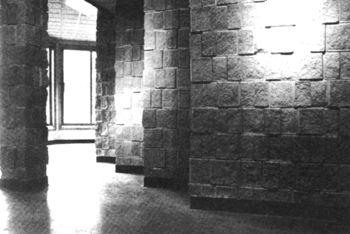
Split Face: A unit with a rough texture on one face - actually produced by splitting a molded unit apart. (i.e. a 16" x 16" square molded block would be mechanically split down the center to create two 8x8x16 units each having a rough face resembling fractured stone).
Split Face Fluted: Similar to split face but with vertical flutes (recesses) in the face. Can include 1-3-5 or 7 flutes per face.
Bold Fluted Split Face: A split textured unit with very deep and wide flutes (recesses) requiring a considerably thicker face shell on one side of the C.M.U. Commonly having 3 central flutes across the block face and 1/2 flute at either end of the face.
Scored: Vertical grooves in smooth face, typically 3/8" square to match vertical mortar joints. Can include 1-3-5-7 scores per face.
Round Flute Face: A smooth face fluted unit with convex sides on the flutes resulting in rounded projections between flutes.
Architectural CMU (Split-faced Fluted - 7 Flutes)
Architectural CMU (Split-faced Fluted - 7 Flutes)
5.3 Screenwall Block: A solution for solar con trol, garden walls, and fences. These blocks have an open web pattern to be used where the admission of air and light is needed in connection with separa tion of areas.
5.4 Concrete Paving UnIts. Concrete masonry units are used for slope paving under highway or railway grade-separation structures and on other steep embankments to prevent costly and often dangerous soil erosion, par ticularly where grass will not grow to protect the surface. They are also used for paving drive ways, access lanes, parking areas, streets, plazas, shopping malls, walks, patios, and floors on grade, to name just a few applications. Pro duced in a range of shapes and colors, paving units are easy to handle and install, requiring only a few tools.
5.5 Grass Grid. Are useful as turf block or "Grass Payers." See Sec. lll/E.2 for illustration. Contact local manufacturers for availability of paving units.
5. Types of Concrete Masonry Units (continued)
5.3 Screenwall Block: A solution for solar control, garden walls, and fences. These blocks have an open web pattern to be used where the admission of air and light is needed in connection with separation of areas.
Examples of Screen Blocks
5.4 Concrete Paving Units. Concrete masonry units are used for slope paving under highway or railway grade-separation structures and on other steep embankments to prevent costly and often dangerous soil erosion, particularly where grass will not grow to protect the surface. They are also used for paving driveways, access lanes, parking areas, streets, plazas, shopping malls, walks, patios, and floors on grade, to name just a few applications. Produced in a range of shapes and colors, paving units are easy to handle and install, requiring only a few tools.
Slope paving units are easily laid to prevent erosion
5.5 Grass Grid. Are useful as turf block or "Grass Pavers." Contact local manufacturers for availability of paving units.
CMU split face texture
Interlocking concrete masonry paver designs
6. Standard Masonry Unit Shapes:
(note: this page will take some time for the images to load)4" CMU
6" CMU
8" CMU
6. Standard Masonry Unit Shapes:
(note: this page will take some time for the images to load)8" CMU
12" CMU
10" CMU
Miscellaneous Shapes